
In the inner cylinder of the receptacle, align the connector to the receptacleĪxis and carefully introduce the connector into the fiber coupler. If you follow th so-called "right-hand orientation rule" you can reproducibly attach and reattach even PM fibers with narrow key receptacle to fiber couplers with wide key receptacle without difficulty.

There is a difference between the receptable and key width for wide key (2.14 mm) and narrow key (2.0 mm) fibers.
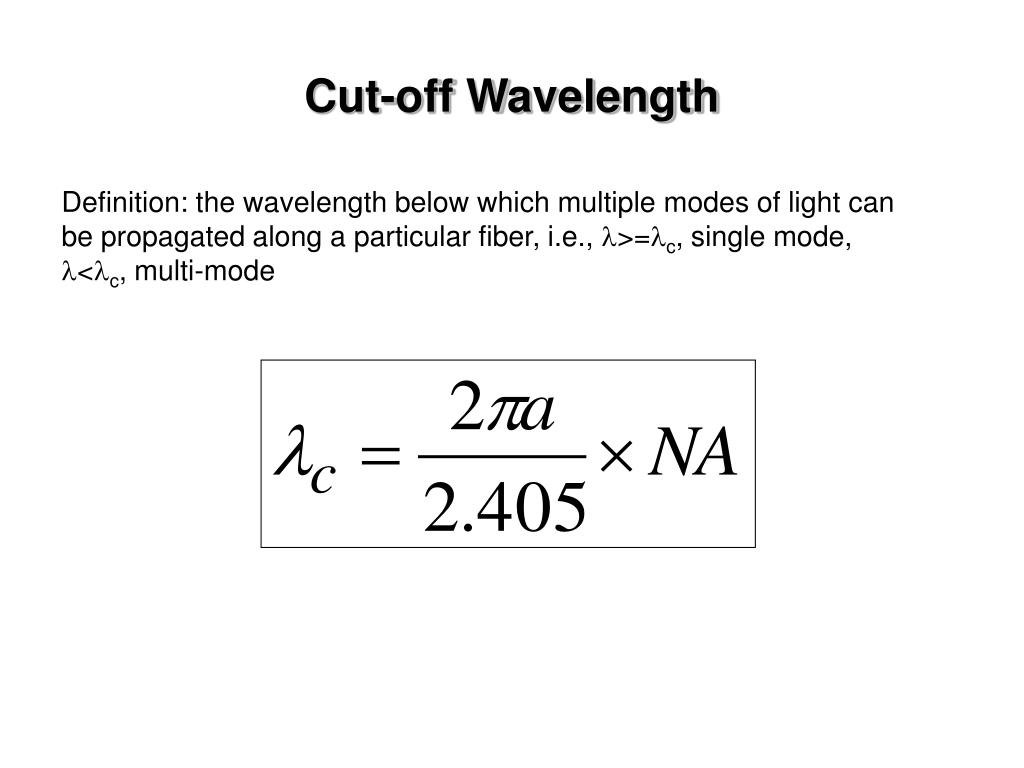
SM CUT OFF WAVELENGTH FREE
The free play in between the connector ferrule and receptacle is only a few microns, but necessary for inserting the ferrule without force.
SM CUT OFF WAVELENGTH PC
Generally, with any FC PC or FC APC type connector there is a freeplay when inserting the fiber into the fiber coupler.

Simply adhere to the "right-hand orientation rule". Without a fiber core to confine the beam, the mode field diameter of the beam already starts to diverge within the fiber end cap, significantly reducing the power density at the fiber end-face.įor FC PC or FC APC type connectors amagnetic versions completely made of titanium can be selected. This means that a short length of fiber (< 300 µm) without a core is spliced onto the single-mode fiber. The fiber connectors can be equipped with an end cap connector. Special fiber connectors are available so that the fiber cable is vaccum compatible down to 10 -7 mbar (only Ø 900 µm buffer fiber cables) or for core-centred fibers. The narrowe key (type "R") fiber connector has an alignment index (key) of 2 mm width. The wide key (type "N") fiber connector has an alignment index (key) of 2.14 mm width. All fiber connectors of type FC assembled by Schäfter+Kirchhoff have an alignment index (key). The single-mode fiber cables are offered as Ø 900 µm buffer in black, or a Ø 3 mm cable in black with Kevlar strain-relief.įor each fiber end the fiber connectors can be selected from a wide range of connector types (FC, DIN or AVIO, E2000, ST (only 0°-polish), or F-SMA (only 0°-polish) with 0°-polish or 8°-polish. concerning the fiber end faces.Īll fiber lengths can be customer specified. Please note that there are other limiting factors e.g. The maximum power level (described by the Brillouin threshhold) that can be transmitted in the fiber is shifted to a higher value.


 0 kommentar(er)
